By a practicing mechanical design engineer — based on Shigley, Machinery’s Handbook, and Marks’
QUICK ANSWER BOX
Bolt torque equation (standard format):T = K × F × D
Where:
- T = tightening torque (lb·ft, N·m)
- K = nut factor (dimensionless, depends on surface condition and lube)
- F = desired bolt preload (lb, N)
- D = nominal bolt diameter (in, m)
Typical K‑factor for steel-on-steel:
- Dry: 0.20 – 0.25
- Lubricated (engine oil): 0.15 – 0.20
- Anti‑seize compound: 0.12 – 0.16
Recommended preload for reusable joints (Shigley):F = 0.75 × Proof Load
Get your exact torque value in seconds with the free calculator at
Table of Contents
1. Opening Hook
A few tenths of a turn too tight, and a steel joint fails by fatigue, leaks under pressure, or shears a bolt in service. Get it wrong, and you’re looking at a warranty claim, a safety incident, or a call from a plant shutdown team. This tutorial gives you the exact steps to calculate the tightening torque that produces a reliable clamped joint—using methods established in Shigley’s Mechanical Engineering Design, Machinery’s Handbook, and Marks’ Standard Handbook for Mechanical Engineers.
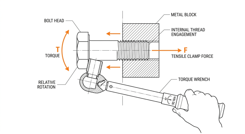
2. The Core Equation
The primary empirical relationship that governs bolt tightening is:
T = K × F × DIn words: Torque equals the nut factor times the desired bolt preload times the nominal bolt diameter.
Variable definitions (SI and Imperial):
- T – Tightening torque, in newton‑metres (N·m) or pound‑feet (lb·ft).
Converters: 1 N·m ≈ 0.7376 lb·ft; 1 lb·ft ≈ 1.3558 N·m. - K – Nut factor (dimensionless). It folds thread friction, collar friction, and minor geometric effects into a single empirical coefficient.
- F – Desired bolt preload (clamping force), in newtons (N) or pounds‑force (lb).
For non‑permanent, reusable joints, Shigley recommends tightening to 75 % of the proof loadFp(the load just below the onset of plastic deformation).
In critical applications where a controlled preload is essential and the joint can be disassembled, Shigley permits up to 90 % of proof load if the joint design accounts for variability. - D – Nominal bolt diameter, in metres (m) or inches (in). For UNC/UNF fasteners, use the fractional inch size directly.
Assumptions and limitations:
- The equation is valid only in the elastic range of the fastener; it does not apply to torque‑to‑yield fasteners or impact‑driven assembly.
- It does not account for gasket compression forces, thread galling, or plastic embedment loss—those effects must be handled separately.
- The nut factor
Kis an aggregate constant; it assumes consistent friction conditions across the thread and bearing surfaces.
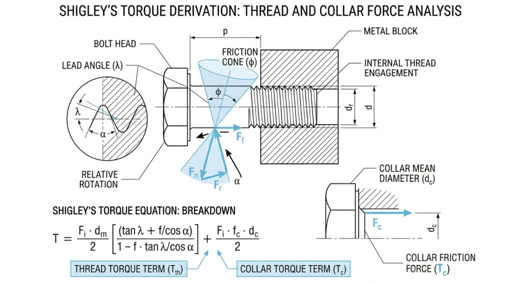
How Shigley expands the model
Shigley’s derivation breaks torque into a thread‑friction component and a collar‑friction component, allowing the user to analyse the effect of lead angle, thread angle, and individual friction coefficients. This is overkill for everyday structural steel connections but essential for high‑consequence joints in pressure vessels, aerospace, and rotating machinery. We will look at the full derivation in Section 6.
3. Variable Deep‑Dive
T – Tightening Torque
Torque is the directly measured quantity you set on a calibrated torque wrench. It is not the clamping force; it is only a means to obtain that force. You will compute it; then you set the wrench to that value.
D – Nominal Bolt Diameter
Look this up from the fastener call‑out: ½‑13 UNC means D = 0.5 in. In the T = KFD equation, use the nominal diameter—not the root or pitch diameter. The approximation is acceptable because the nut factor K is tuned to the nominal diameter for a given thread series.
F – Preload
Preload is the tensile force in the bolt that clamps the joint members together. For a reusable joint, Shigley’s proof‑load method gives:
F = 0.75 × Fpwhere Fp (proof load) = proof stress × tensile stress area At.
- Proof stress is a material property specified by the bolt grade (e.g., SAE J429 Grade 5: 85 000 psi). Obtain it from Machinery’s Handbook or ASTM standards.
- Tensile stress area
Atis a calculated value tabulated for every standard thread size. For a ½‑13 UNC bolt,At= 0.1419 in² (from standard tables in Machinery’s Handbook or Shigley’s appendix).
Thus, for a Grade 5, ½‑13 bolt:
Fp = 85 000 psi × 0.1419 in² ≈ 12 061 lb
F = 0.75 × 12 061 ≈ 9 046 lb
If the joint requires higher preload, move closer to the 0.90 factor—but always respect the proof load boundary.
K – Nut Factor
This is the most commonly misapplied variable.K captures how much of the input torque goes into stretching the bolt versus overcoming friction. A change in lubrication or plating alters K drastically.
- Look‑up source: Machinery’s Handbook provides a table of “Nut Factors” for various surface conditions (dry steel, oil‑lubricated, grease, anti‑seize, etc.). Typical dry steel‑on‑steel K ≈ 0.20; lubricated with engine oil K ≈ 0.15–0.18.
- Shigley’s derivation: K can be derived from thread geometry, lead angle, and friction coefficients
μ_t(thread) andμ_c(collar). If you know those coefficients, you can compute K analytically—but in practice, use the tabulated values unless you have measured friction data.
Tables to support quick look‑ups (add these before the worked example for immediate utility):
Table A: SAE Bolt Grades – Proof Stress & Yield
| SAE Grade | Nominal Size (in) | Proof Stress (ksi) | Yield Strength (ksi) | Typical Use |
|---|---|---|---|---|
| Grade 2 | ¼ – ¾ | 55 | 57 | Low‑stress, general hardware |
| Grade 5 | ¼ – 1 | 85 | 92 | Automotive, structural, medium strength |
| Grade 8 | ¼ – 1½ | 120 | 130 | High‑strength applications, heavy machinery |
Table B: Tensile Stress Area (At) for Coarse Threads (UNC)
| Size (in) – TPI | At (in²) |
|---|---|
| ¼ – 20 | 0.0318 |
| ⅜ – 16 | 0.0775 |
| ½ – 13 | 0.1419 |
| ⅝ – 11 | 0.226 |
| ¾ – 10 | 0.334 |
For instant preload and torque values across all grades, use the free Bolt Torque Calculator at Torque Calculator. It automatically selects the correct proof stress and tensile area.
4. Worked Example
Fastener: ½‑13 UNC bolt, SAE J429 Grade 5, assembled with engine oil as the lubricant.
Joint type: Reusable, non‑permanent steel connection.
Method (a): Simple K‑factor method (T = K × F × D)
- Choose preload F — for a reusable joint we want about 75 % of proof load. Let’s use F = 9 000 lb (a round approximation from the proof‑load calculation that follows).
- Select K — for engine oil on steel, Machinery’s Handbook indicates K ≈ 0.18.
- Insert D = 0.5 in.
T = 0.18 × 9 000 lb × 0.5 in = 810 lb·inConvert to lb·ft: 810 ÷ 12 = 67.5 lb·ft.
In SI: 810 lb·in × 0.113 N·m/(lb·in) ≈ 91.5 N·m.
Plain‑English interpretation: Set your torque wrench to 68 lb·ft (92 N·m).
Method (b): Shigley’s proof‑load method for precise preload
- Look up proof stress for Grade 5: Shigley, Table 8–9 → 85 000 psi (see Table A above).
- Look up tensile stress area
Atfor ½‑13 UNC: Table B → 0.1419 in². - Compute proof load:
Fp = 85 000 psi × 0.1419 in² = 12 061 lb- Determine preload for a reusable joint:
F = 0.75 × 12 061 = 9 046 lb- Apply T = KFD with K = 0.18 (engine oil):
T = 0.18 × 9 046 lb × 0.5 in = 814.1 lb·in814 lb·in ÷ 12 = 67.8 lb·ft
814 lb·in × 0.113 ≈ 92.0 N·m
Final answer: 68 lb·ft (92 N·m). The two methods agree because the simple method already assumes a 75 % preload target. This example shows why the Shigley method is robust—it ties preload directly to the fastener’s mechanical properties, removing guesswork.
![Worked example torque diagram: A torque wrench with digital readout showing 68 lb·ft, alongside a half-section bolt joint with labeled preload force F and friction zones. Clean vector style, navy blue and grey.]
If you’re working with a different bolt size, grade, or surface condition, recalculating from scratch every time is tedious and error‑prone. Our free Bolt Torque Calculator at mechconcepts.tech handles any combination of bolt spec, grade, and K‑factor instantly—using the same Shigley methodology you just worked through.
Try the Bolt Torque Calculator →
5. Reference Table: K‑Factor by Surface Condition
| Surface condition | K‑factor range | Typical use case | Risk if wrong |
|---|---|---|---|
| Dry steel (as‑received, clean) | 0.20 – 0.25 | General structural connections, no lube | Large scatter → inconsistent preload, possible under‑torque |
| Lubricated – engine oil | 0.15 – 0.20 | Field assembly, typical maintenance work | Switching to dry → K ≈ 0.20 → lower preload for same torque |
| Lubricated – grease | 0.12 – 0.18 | Shop assembly, controlled environment | Over‑torque if dry value is used; risk of bolt yield |
| Anti‑seize compound | 0.12 – 0.16 | High‑temperature or stainless joints | Extremely low K; torque‑wrench setting must be reduced |
| Cadmium‑plated (dry) | 0.16 – 0.20 | Corrosion‑resistant, aerospace | Plating wears; K changes over repeated assemblies |
| Zinc‑plated (dry) | 0.18 – 0.22 | General fasteners, light corrosion resistance | Similar to dry steel; confirm with actual torque‑tension test |
Not sure which K‑factor applies to your joint? The calculator includes a condition selector that picks the right K‑factor automatically.
Open Calculator →
6. Shigley’s Method — Deeper Look
Shigley’s full torque analysis splits torque into two contributors:
T = F × [(d_m / 2) × tan(λ + φ) + (μ_c × d_c / 2)]where:
- d_m – mean (pitch) diameter of the thread
- λ – lead angle = tan⁻¹(lead / (π × d_m))
- φ – friction angle for the thread = tan⁻¹(μ_t)
- μ_t – coefficient of friction between mating threads
- μ_c – coefficient of friction at the nut or bolt‑head bearing face
- d_c – effective bearing (collar) diameter
(The true Shigley formulation includes the thread‑angle effect by replacing φ with φ’ = tan⁻¹(μ_t / cos α), where α is the half‑angle of the thread form. For UN threads, α = 30°.)
When this precision matters:
- Pressure vessel flanges, rotating machine bolted joints, nuclear bolting applications
- Any joint where failure threatens life, and the preload scatter must be held below ±5 %
- When you have measured friction coefficients (from torque‑tension testing) rather than generic K‑factors
When T = KFD is sufficient:
- Structural steel connections (AISC‑compliant)
- General machine frames, brackets, guards
- Maintenance work with lubricated fasteners and a calibrated torque wrench
he calculator on mechconcepts.tech embeds the full Shigley logic in the background—so you get the accuracy of the threaded‑joint mechanics without needing to solve the tan(λ+φ) equations every time.
7. Common Mistakes
- Using the wrong K‑factor for the surface condition
Why it happens: K‑factors are taken from memory or a generic “0.2” rule without checking lube state.
Consequence: Torque may feel correct but preload is seriously off—joints loosen or bolts yield.
Correction: Always look up or measure K for the exact surface/lubricant combination. When in doubt, run a torque‑tension test. - Ignoring the difference between torque and preload (over‑torquing ≠ more preload in the plastic range)
Why it happens: The thinking “more twist equals more clamp” ignores that once the bolt yields, extra rotation adds no appreciable preload.
Consequence: The bolt necks and eventually breaks during assembly or early in service.
Correction: Respect the proof‑load limit; use torque‑to‑yield fasteners only when the procedure is engineered. - Applying lubricated torque specs to dry‑assembled joints
Why it happens: A technician uses the torque value from a lubricated procedure but assembles the joint without lube.
Consequence: Because dry K ≈ 0.20 is higher than lubricated K ≈ 0.15, the same torque produces lower preload—joint slip or fatigue failure.
Correction: Always verify lube condition. If the fastener must be dry, recalculate torque with the appropriate K‑factor. - Not accounting for bolt relaxation / embedment loss after assembly
Why it happens: Surface roughness peaks flatten, paint/primer creeps, or gaskets relax after initial tightening.
Consequence: Up to 10–20 % preload loss within hours, enough to cause leak paths or loose connections.
Correction: Consider a retorque sequence after initial run‑in, or apply an embedment loss factor in the preload target. - Using the wrong grade’s proof stress
Why it happens: Grade 8 bolts look similar to Grade 5 in a dusty toolbox.
Consequence: A torque value calculated for Grade 5 will under‑preload a Grade 8 bolt (or over‑preload a Grade 5 if mistaken for Grade 8).
Correction: Identify markings per SAE/ASTM. If uncertain, torque to the lower grade’s limit. - Measuring torque with an uncalibrated wrench or on a distorted thread
Why it happens: Older click‑type wrenches drift; damaged threads increase friction.
Consequence: Torque reading is meaningless, preload scatter explodes.
Correction: Calibrate torque wrenches annually. Chase or repair threads before assembly.
8. Quick‑Reference Summary Box
- Core formula: T = K × F × D — torque equals nut factor times preload times diameter.
- Preload in reusable joints: Use 0.75 × proof load (Shigley); up to 0.90 for critical, controlled applications.
- Proof load: Obtain proof stress from bolt grade (e.g., 85 000 psi for Grade 5) and multiply by tensile stress area
Atfrom standard tables. - Nut factor K: Depends on surface condition and lubrication; Machinery’s Handbook lists typical ranges from 0.12 (anti‑seize) to 0.25 (dry steel).
- Torque limit: The equation is valid only in the elastic range; never use it for torque‑to‑yield fasteners.
- Common pitfall: A lubricated K‑factor applied to a dry joint can reduce preload by 25–30 %.
- Free Calculator: Skip the manual math — use the Bolt Torque Calculator at mechconcepts.tech for instant results on any bolt spec, grade, or surface condition.
9. Frequently Asked Questions
What is K-factor in bolt torque?
K‑factor (nut factor) is an empirical coefficient that lumps together all frictional and geometric effects that convert input torque into bolt preload. It typically ranges from 0.12 (well‑lubricated) to 0.25 (dry, as‑received).
What torque should I use for lubricated bolts?
You must use a reduced K‑factor (0.15–0.20) in the T=KFD formula. For a ½‑13 Grade 5 bolt with oil, the torque is around 68 lb·ft. Always recalculate for your specific diameter and grade.
Why does lubrication reduce torque?
Lubrication lowers the coefficient of friction at the threads and under the bolt head. This means less torque is needed to achieve the same preload; using a dry torque value on a lubricated bolt can yield the bolt.
Can I use T = KFD for stainless steel bolts?
Yes, but you need the correct K‑factor. Stainless-on-stainless threads are prone to galling. Typical K‑factors for dry stainless are higher (0.25–0.35). Anti‑seize can bring K down but may affect joint relaxation.
What is proof load?
Proof load is the maximum tensile force a bolt can withstand without developing a permanent set (yield). It equals proof stress × tensile stress area. Shigley’s method limits preload to a fraction (75–90 %) of proof load to keep the bolt elastic.
What happens if preload is too low?
The joint may loosen under vibration, slip under shear loads, or leak if a gasket is present. The clamped members can separate, leading to bolt fatigue and failure.
10. Closing Paragraph
Correct preload is what turns a threaded fastener into a reliable joint—it keeps the clamp force high enough to resist vibration, pressure, and shear. The T = KFD method, anchored in Shigley’s proof‑load approach, gives you that control when you dial in the right values. In an assembly bay or design review, you rarely work with just one bolt spec, and having to pivot between different sizes, grades, and lubrication conditions makes manual calculation impractical at scale.
Bookmark the free Bolt Torque Calculator at mechconcepts.tech — it’s built on the same Shigley methodology this tutorial covers, and it takes 10 seconds to use.